
Looking at the GPIO diagram, pull is attached after direction (input disconnect isn't shown explicitly on the input buffer but the intention of that is to disconnect the read circuit, not to prevent pull, you often need to pull a pin you don't need to read). The nRF52 DK supports a Near Field Communication (NFC) tag. You're explicitly attaching a pulldown to the pin.

In FCC 15.247-2 it is said 'The minimum 6 dB bandwidth shall be at least 500 kHz'. If the pin is DRIVEN, ie S0S1 it means a totem pole configuration where the pin is actively pulled to '0' or '1'. Dear Nordic, I are using nrf52832 to develop a product that needs FCC certificate, We use a PA and can increase the output power up to 20 dBm and it seems that is lower than FCC limitations (its 21 dBm). Ill have to refer to the RT8471 datasheet to see if the IAdj pin is specified for capacitance or other parameters, but I wouldnt worry even with 8+ fanout.

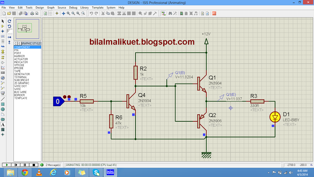
High drive means 5mA, low drive means 1mA (or 2. The average Arduino output is also fairly high current so it can totem-pole a reasonable number of logic inputs.
Nrf52 totem pole output pdf#
To debug an external board with SEGGER J-Link OB IF, connect to the Debug out connector ( P19) with a 10-pin cable. Request Motorola MC33066P: High performance resonant mode controller online from Elcodis, view and download MC33066P pdf datasheet, Motorola specifications. Don't think of voltage, think of current. The nRF52 DK supports programming and debugging nRF51 and nRF52 devices mounted on external boards. The Debug in connector ( P18) makes it possible to connect external debuggers for debugging while running on battery or external power supply. The nRF52 DK is equipped with a small size coaxial connector ( J1) for conducted measurements of the RF signal. The current drawn by the nRF52832 device can be monitored on the nRF52 DK. Echa un vistazo a nuestra selección de tótem pole book para ver las mejores piezas hechas a mano, únicas o personalizadas de nuestras tiendas. NRF52832 can use an optional 32.768 kHz crystal (X2) for higher accuracy and lower average power consumption. I use the recommended hardware configuration, with a charging output P0.26 connected to each pad through 100k resistors, and each pad wired to an ADC input (please see setup below).
Nrf52 totem pole output code#
The four buttons and four LEDs on the nRF52 DK are connected to dedicated I/Os on the nRF52832 chip. I am working on a capacitive sensing application using the SAADC module and csense code on the nRF52 DK (SDK v14.2). The P1 connector provides access to ground and power on the nRF52 DK. The nRF52 DK has three power options: 5 V from the USB, external power supply, and coin cell battery.Īccess to the nRF52832 GPIOs is available from connectors P2, P3, P4, P5, and P6. The nRF52 DK block diagram shows the connections between the different blocks. high-isolation single-pole dual-throw (SPDT).
Nrf52 totem pole output series#
which are optimized to boost the link budget of the nRF52 and nRF53 Series advanced multi-protocol wireless SoCs. NRF52 DK hardware drawings show both sides of the PCA10040. Mikroe Gyro 6 Click features the TDK InvenSense IAM-20380 3-axis digital-output X-, Y-, and Z-axis angular rate sensor (gyroscope).


 0 kommentar(er)
